
First Things First
In order to get an air cannon to release enough air to make that large startling sound, we’ll need an air trigger that can pass a massive amount of air at once. To keep our costs under *totally ridiculous*, I turned to the washing machine water valve that has been used for air valves since Carl Chetta of the Trash Can Trauma fame introduced it’s creative use some time in the 1990’s. I was determined to use one for my cannon, but I knew it would take some work, as the valve you see above without modifications will not expel enough volume to scare much of anyone. The particular brand and or model valve above wound up being the very best one out of many different ones that I had to test to bring these plans to this web page. This translucent white unit I purchased many years ago in a bag of 10 random valves is a Horton C539 / N-6042 model and was the only one I have EVER seen. Since I found it impossible to find another like it I knew that the likelihood of you finding one was between slim and none as well, so I needed an alternate that you could use for a good result.
Luckily, the most abundant of all the water valves used, model #N-51 (which is usually blue in color, but can be found in others as well) can be modified to work just fine. Whether it is stamped Maytag or some other manufacturer’s name, the N-51 is the model. And it is the ONLY other model I could find that would operate under the pressure needed to make this project work.
Note; There are other plentiful valves out there besides the one we recommend here, the N-51, but the big difference is they read N-50 and they DO NOT work at this pressure. I am stressing this point so that you don’t waste your time with dishwashing valves or some other type than the two I show here, as after dozens of different tests I have yet to find even one that will do the job when placed under more than 50 lbs of pressure.
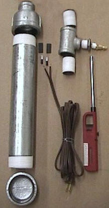
This is a single-shot cylinder for the cannon, so if you plan to trigger yours twice in rapid repetition you should increase all of the 2″ fittings here to 3″ fittings which will give you enough for two full firings. You will notice right away I am showing a 1/4″ close fitting and female air coupler instead of just a male coupler, and that is because I didn’t have the male during this photo layout. It will work as well either way. The tools you will need for this project are a heat gun or lighter, a drill, a 3/4″ drill bit, 3/8″ drill bit, electrical crimp tool, two monkey wrenches, a die grinder and a crescent wrench.
Shopping List
(1) 12″ length of 2″ galvanized pipe
(1) 2″ galvanized pipe end cap
(1) 1/2″ to 2″ galvanized pipe reducer
(1) 1/2″ to 1 1/2″ galvanized pipe reducer
(1) female hose to FIP swivel fitting 3/4″ x 1/2″
(1) lawn hose end cap
(3) 1/2″ short threaded nipple
(1) 1/2″ galvanized pipe T fitting
(1) 1/2 to 1/4″ galvanized reducer bushing
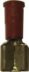
(1) 1/4″ IID male air coupler
(1) 6′ extension cord
(2) 1/4″ female quick slide, 18 ga. crimp cord fittings
(1) washing machine water valve
Let’s Get Our Air Cylinder Together
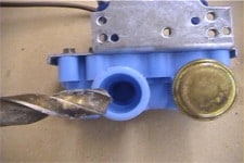
You can see the hardware fittings are laid out here how you will want to connect them. Later this assembly will be attached to the inlet of the water valve closest to the outlet nozzle. Be sure to use teflon plumber’s tape on all the threads of our fittings and make sure all of your connections are very tight, as this will be under high pressure. Attach the end cap to one end of the pipe and the reducer to the other. Then once you assemble the two close 1/2″ threaded fittings to each end of the T fitting, install the air nipple and 1/4″ to 1/2″ reducer to the right angle of the same. Screw this in tight to the 2″ to 1/2″ reducer.
A Little Surgery To The Water Valve
As you can see, the outlet of our valve is a 3/8″ nipple that was meant to be attached to a water hose.
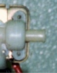
For three reasons we will need to remove this nipple and I have found the easiest way to do that is drill directly into the nipple from the end using a 3/4″ forstner bit
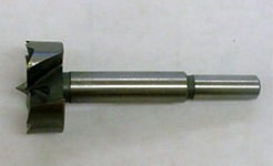
which will stop with a flush cut just below the plastic, where you will find hiding, a black washer with a small hole in it.
This I believe is some sort of anti surge to regulate the flow of water should there be a change in pressure. However this is one of a few things keeping our valve from discharging a large enough blast of air to make a serious report. Remove this and give it a toss.

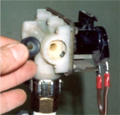
Using your 3/8″ drill bit, drill out the small port hole behind the washer as shown here in a photo where we were converting an N-51 valve for a cannon.
You will need to drill this back past the inlet port inside the valve that is coming up from the cylinder . On the same valve I show doing the same thing to the inlet port. Note that this is the closest inlet port to the exhaust port as mentioned earlier.
The brass cap you see to the right of this shot is a steel lawn hose end cap that I recommend using if you have a choice between the plastic one I used on my first prototype which you will see later. Okay! Now your valve will actually dump out enough air to make a startling sound.
The plastic hose end cap shown here can be found in the garden section of your hardware store.
The steel one above will be found in the hose fittings section next to the black and galvanized pipe as will the Female Hose-to-FIP fitting shown on the left side of the valve. Since these both seat against rubber washers, you will not need to use teflon tape on the threads of the water valve. Now to attach your power cord to the same solenoid as you are using for the release valve, chop off the female end of your extension cord and fit your 1/4″ quick slide fittings using a crimp tool.
Not shown in the photos here are the heat shrink tubes I put over these connections after I attach to the prongs on the water valve to prevent an electrical shock.
Assemble The Valve To The Cylinder
Once completed, thread the entire assembly into the top end cap of your cylinder tightly. Remember to use teflon tape on the threads going into the bottom of the FIP fitting. I also recommend zip tying the electrical cord to the T fitting nice and tight to prevent the power cord from becoming unplugged to the valve.

In this shot you can see where I have taken a 2″ x 1/2″ threaded fitting and inserted one end into a T fitting to use as a handle as I prepare to make a thread tap. Then the end remaining I used a die grinder to slot the sides in 4 places, about 1/2″ up.
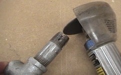
When I make the cuts I keep the grinder on a angle to the fitting so that the slots will create sharp front edges to the threads which I will need to cut into plastic as well at route the shavings to the inside of the fitting and away from our new threads. Prior to this, I also ground down the threads of the fitting back about 1/2″ on a taper. The very end threads are ground off, making it small enough to insert into a 3/4″ hole such as we now have in the exhaust of our water valve. We will be using this thread tap to cut in threads into the exhaust port of the valve so we can insert a 1/2″ short threaded fitting.

Once that is done simply screw your 1/2″ to 1 1/2″ reducer fitting onto it for a megaphone. This was the result of quite and array of ideas tested in order to bring more of a Bang! sound to this cannon, and it certainly makes a decided difference! Not only that, but the new extension away from the body of the cannon means we can now drill a hole in the wall of our haunt, mount this cannon on the back side of it with the exhaust bell just sticking out, allowing us to hide this in plain sight down halls and in rooms where ever we desire!
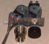
All Assembled

In this shot you can see we have added an additional item to the build of this cannon. Not that it is necessary if you are using your regulator on your compressor tank to keep the air at the necessary 70 to 80 PSI this cannon works at. However, if you want to have the convenience of running your air line at a higher rate so you can feed air out to multiple props, installing a dedicated air regulator is a great idea. Of course this and the fittings needed here were not part of the initial how-to steps and parts list, since air cannons do not come equipped with this feature and doing so would clearly make this not a $20 investment. In the event you wish to add one to yours, I included the info here in the Additions section of our how-to. This will add about $13 to your initial investment should you choose to spring for the luxury.
Safety Addons
Here is a photo of the compact regulator I use on all of my animatronics. It is a Harbor Freight 1/4″ Air Regulator with gauge and is NOT to be confused with an Air PRESSURE regulator sold for a few dollars less at the same store.

The diaphragm regulator works like the unit on your air compressor, releasing a total air pressure as shown on the gauge and never more than that. An air pressure regulator is a FLOW regulator only. Meaning that if you have a flow regulator adjusted to 28 lbs and are sending 105 lbs of pressure going into the intake AND keep the air flowing through constantly, the pressure coming out will stay at 28 pounds. But once you stop this flow, the pressure that backs up against its inner mechanism allows the full blast of pressure you have going in to be emitted initially, until the flow stabilizes. Thus, if you have an animatronic that works on 28 lbs of pressure such as the Exorcust, a PRESSURE regulator, if left hooked up to 105 lbs of direct pressure will send your puppet through it’s cycle about 4 times as fast as needed and probably through the ceiling. Funny as hell for a just a moment until you realize you have to replace all its working mechanism and patch that hole in your garage roof. So be sure you are buying a DIAPHRAGM regulator.

To add the regulator you will need a 1/4″ ‘close” threaded fitting (In the shot above I used a 1 1/2″ fitting and it didn’t really need to be that long) to space away from the reducer, a 1/2″ 90 degree elbow, a 1/4″ threaded fitting and a female IID quick coupler, rather than the male one used on the $20 cannon. The regulator used here comes from the factory set up with swivel style connectors for both the air IN and OUT which look different from standard pipe thread fittings, but they are the same thread and can be used with standard fittings. I have been confused regarding these swivel fittings for a long time myself but after extensive research, I found these type connectors are usually used with swivel-end air hoses only. Swivel fittings and adaptors are not largely made with these flared and concave ends, because their use is primarily stationary and do not need to swivel during use. You can simply use a 1/4″ male pipe fitting in to the swivel female and tighten it up tight and it will seal even though your pipe fitting does not have a concave end. On the male side you will need to wrap the threads very heavily with Teflon plumber’s tape to get that to seal well for some reason. I use enough wraps that you can no longer see the threads below the tape. Then when I attach the coupler it pulls up tight.
As a side note here of caution, remember you are using highly pressurized air being released very quickly which could easily damage a person’s eyes or ear drums if fired too close. Be sure to keep the cannon mounted at waist level or lower so you don’t put your victims at real risk.