
I have always wanted a life-size dummy that was not only poseable but re-poseable and had a self-contained power source that could be used for countless animations. He needs to be able to stand on his own and could instantly be repositioned to sit or kneel etc. However, as of yet, I have never heard of a way to achieve such an animal.
With a lot of thought and testing in the fall of 2001, I developed a puppet that would do just these things. With a special joint I developed specifically for this build the dummy is able to stand up stable under his own weight while the joints remained adjustable without any tools. They can also be adjusted to allow his built-in motor to make him stir a boiling kettle or any number of other full-motion movements. Here’s how I did it.
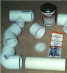
In the photo here you can get a good look at many of the items needed for the skeleton of your dummy. It is fair to note that the need for the PVC adhesive is purely to adhere the caps that cover the openings in each side of the hips assembly. This is not needed and can save you a few dollars off the cost of constructing this guy.

Included in this how-to are the full instructions on how to make your dummy animated with the addition of an oscillating fan motor. This element is purely secondary to the dummy’s construction, as the fan in no way changes the construction of the dummy with the exception that his pelvis would be a straight section of pipe instead of a T fitting to hold the base of the fan. So whichever way you choose to make yours, the body remains the same in dimensions and fittings with that single exception.
Here is a list of items with cut-out dimensions that you will need to build your very own Death Lord Dummy.
Parts List
(1) Howard or Holmes brand 12″ fan
(1) Head
(24) 5/16″ x 3 1/4″ eye bolts
(12) 3/8″ x 1 1/2″ course thread bolts
(48) 3/8″ course thread lock nuts
(48) 5/16″ flat washers
(12) 3/8″ course thread lock nuts
(24) extra heavy, 1/2″ cut washers
(13) 3/4″ #8 pan head screws
(1) flat aluminum stock, 1/8″ x 1/2″ x 12″ long
(2) 3/4″ thick boards, 5″ x 12″
(4) 1″ PVC slip-on pipe caps
(1) can PVC adhesive
1 1/2″ PVC Pipe Fittings
(5) “T” fittings; all female, all slip
(20) End caps; female
(1) “T” fitting with the center opening for 1″ pipe
(2) 90 degree Elbows; all female, all slip
(4) 45o Elbows; all female, all slip
(2) Test caps; male (find in the ABS pipe section)
1″ schedule 40 PVC pipe
(2) 2 1/2″ (hand)
(1) 17″ (neck)
1 1/2″ schedule 40 PVC pipe
(8) 2 1/2″ (shoulders, ankles)
(2) 3″ (top chest)
(2) 4″ (groin)
(2) 4 1/2″ (upper arm)
(2) 5″ (middle chest)
(2) 8″ (fore arm)
(2) 10 1/4″ (stomach)
(2) 12″ (lower leg)
(2) 13″ (upper leg)
The Build
The first thing we will do is prepare your fan for service. You will begin by removing the cage & fan assembly and motor cover. You have likely heard that oscillating fans do not last when used to move the head or some other portion of an animatronic, especially when the fan itself has been removed. I have found that the secret to long life (5 years and counting) for your fan motor is ventilation. We are removing the motor cover so air can circulate around it for cooling and when we ultimately dress our dummy we will leave an opening at the top of the chest (through the neck) for the hot air to escape.


Do these things and you should be as fortunate as I have. Also, note the brand and size of this fan is particular, as not all oscillating fans can be used in this fashion, as some, such as the Holmes 16″ model has an integrated motor cover that functions as part of the working mechanism, so the cover simply cannot be removed. I found that there is some work to the cover since the on/off switch was wired after the cover was screwed on and the wires intertwine with the mounting bracket inside. To get this off I had to cut the back of the mounting bracket out to clear the wires for its removal. I then zip tied the switch, sans knob, to the other wires there on the top of the motor as tight as I could snug it in.

Now we will cut off the nipple that sticks out that the fan and cage attach to. You can use a hacksaw for this or a pneumatic cut-off tool. Once you get to the fan blade shaft itself you will have to hold the shaft with a pair of vise grips to cut it off with a hacksaw or a die grinder cut-off tool as shown here. Keep your cuts as close to the motor housing as possible or go back over the portions left sticking out with a grinder to smooth it all out so there are no sharp things that will grab the clothes you will be dressing your dummy in.
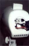
I cut a couple of sections of aluminum stock that was 1/8″ x 1/2″ x about 5″ long apiece to attach to the motor housing into the threaded hole on each side of the motor shaft that the fan cage used to attach to. I bent an 80 degree turn a couple inches up on each, making sure that I bent one to the right, and one to the left so they would be able to cradle the 1″ PVC pipe “neck” that I wanted to be centered directly above the pivot point of the motor. If the neck is located further away from the front than here, the head of our dummy will sweep to the left and right instead of pivot, like Linda Blair. And we all know we want to do it like Linda does. I used the same screws that came out of the holes to attach my two neck braces. Then just tweak the braces until they are a perfect fit to the pipe while in a plumb vertical position. (I meant to use the word plumb here as in perfectly vertical to the earth and not as in the more often referenced use as in “I was plumb hammered when I told him to shove it and he left me plumb worked all over like this..” These are different meaning all together. Back to the neck, just attach a 1″ section of PVC pipe 17″ long to the braces with 2 screws in each (I used 3/4″ x #8 pan head screws) as you can see here. We will cut off the excess neck length after we are completed with our project and install the head.
Next, remove the steel shaft (that came with the fan) that goes up inside the section of plastic pipe that the fan motor is attached to, cut this off at 4 1/4″ long. Notice in the picture above the “cut shaft here” is shown with the top line at where the steel shaft begins once inside the motor mount. I use this photo here only to clarify what item needs to be cut down. The amount left sticking out of the motor mount that we will be inserting into our dummy’s fitting will be about 2″.
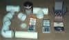
Before our dummy can begin to take shape, we will need to assemble all 12 of his joints. This will entail preparing the pipe cap fittings with the necessary 5/16″ hole in the center of each. Also you need to assemble the joints and attach them to each cap. Here you can see how each section goes together.
At the top of the blow up of the joint above shows two regular nuts on each side of two flat washers with a lock nut between each pair of nuts. My idea was to really lock the connection tight when attaching to the PVC cap. However, after this photo was taken, this proved to fail in use (after I had fully assembled all 12 joints and installed them) so I recommend following the layout shown in the top photo for the actual pieces used. Lock nuts are required for all these connections so they won’t loosen up during use. When assembling your joints you will need to spin a lock nut on the eye bolts threads with the plastic locking part of the nut to be threaded on first. Since this plastic does not have threads in it until it contacts the bolt, you need to thread each one on the bolt with the flat side first and then thread it clear to the end of the eye bolt to really cut in the threads to this plastic.
Back it off and then it should spin right on with the flat side pointing the other way so your connection to the pipe cap will be as tight and strong as possible. One more point is the spacer that fits inside the two eye bolts needs to have the teeth on the outside of it ground off till each one fits inside each eye bolt perfectly with no real slop as well as being able to spin inside without catching or hanging up. This must be a good fit. If you can find a section of pipe to act as the spacer here that is already a perfect fit that I couldn’t find, remember that this must be thick enough to go almost to the full width of both eye bolts while together. It needs to be recessed slightly for the cut washers to have space to bow in slightly. The 1/2″ hex nuts I found are the perfect thickness and with the teeth ground off are the perfect diameter as well.
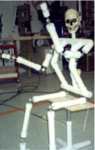
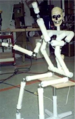
In the photo here you can get a really good idea of how our poseable dummy is constructed. As covered in the materials list, the PVC pipe you see is 1 1/2″ schedule 40 and the joints are made up of a combination of the eye bolts, bolts, washers and lock nuts covered in our last section. There were portions of the dummy that needed to be constructed more than once to get him as stable as he needed to be including going to the heavy duty hardware that you see suggested in this how-to. Once completed however, he worked as well as you could ask for. Just make sure your connections to the PVC pipe caps at each joint are as tight as you can possibly make them.

Since all of your pieces to his skeleton were cut to length, all we need to do now is assemble him. Your torso should look like the photo on the above right when you are done. You’ll notice we have the fan motor facing forward here to move inside the cavity we will create for the chest by angling the chest pipes out away from the “body”. Once your dummy is dressed the fabric will be suspended clear from the movement of the motor. Using the above photo on the left as also an item reference, lets begin.
First we will insert one of the main pipe sections (1 1/2″) 2 1/2″ long between a shoulder 90 degree (#1) and a T fitting (#3) and hammer together till there is no space between the two fittings. These two will be facing outward both at about a 35o angle. Then use another 2 1/2″ pipe into the end of the T and attach another T, only this one will be pointing down. We will use this for the neck of the dummy. Then another 2 1/2″ section and another T to that, parallel to the first T. Then finish off the shoulders with another 2 1/2″ pipe and the other 90 degree shoulder. When done your shoulders should be 19 1/2″ wide.
To complete the chest section, notice that the two chest pipes travel out away from the body and also in a widening pattern. This could be changed to vertical by shortening the pipes that go between his groin T (#5). For this how-to we will follow the photo. Insert a 3″ section of pipe now to each of the Ts in the shoulders that are pointing forward 35o. Then hammer on to that a 45o pipe fitting (#4) that you will turn out away from each other just slightly. Into these hammer in the front of the chest pieces (D) which are 5″. To these add another 45o fitting pointed downward and slip in the stomach pipe section (E) that is 10 1/4″ long. On to each of the now completed chest sections hammer on a T. To the inside of each opposing T hammer in a 4″ groin pipe and join these two with the T fitting that has the 1″ pipe outlet in the center. When done your hips should be 17″ wide.
At the center of the middle T of the shoulders, you will need to drill a hole for the 1″ PVC pipe neck attached to the fan motor assembly (#9) to pass through. Make sure this hole is perfectly centered with the opening of the T that is pointed downward. Once cut, slide your fan assembly up through the top T and the hole you just cut, then back down into the 1″ opening of the bottom T (#5). If your lower pipe of the fan assembly was cut to the right length then it should fit all the way down into the lower T until it is flush with motor mount section of the fan. Adjust your torso so that the shoulders and hips are parallel with each other and the assembly is square and level. The fan motor assembly should run smoothly with no binding of any kind once plugged in. After you get this all true, pre-drill small holes in each pipe / fitting connection and screw in a #8, 3/4″ screw to keep your pieces from migrating.
For each of the arm and leg sections simply hammer the cap with the joint fitting attached to each of the corresponding pipe sections as referenced in the cut out list. Note that the hands are 2 1/2″ sections of 1″ PVC pipe with the small 1″ caps on each end. You can then insert this into the palm area of a prop hand and attach the hand with screws into the PVC.

In the pic here you will see an alternative construction of the dummy’s legs. Once together and standing our dummy I realized that the stability I had with the poseable feet was somewhat less secure than I may desire. If I were using my dummy in a seated position or as a wall-crawler I would use the joints at the ankle as the main photo shows. But if I will be posing my dummy standing at all times, I recommend using this assembly shown here. This requires the 19″ shin bone pipe section talked about on the cut out list page. Your dummy will be very stable to stand upright on his own this way.

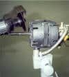
Here is a poor photo of how your fan motor assembly should fit between the hips and shoulders. Note the screws attaching the pipe from the motor mount to the 1″ opening of the lower T fitting.
Now you have only to dress him and set him up with the head of your choice. I used mine without a head once I had him fully engineered.
So far I have not fitted this powered dummy with any other moving parts, but with the oscillating fan motor, you could easily attach a bicycle cable to the motor and use this power to move arms to stir a kettle or legs to ride a bicycle or wherever your imagineering takes you! Please post a pic of your version of the Death Lord Dummy, as we will be putting these up on our website for others to see where the dummy can take them!