I had been tinkering around with the idea of making Phantasm’s coordinate ghost system more
simple (ie: cheaper) for the standard home haunt. This system though would not be able to support
an FCG as their indoor system could. So, this is my page on how-to make a flying ghost though an
axworthy system would be much simpler.
After modeling a few different ideas, it came apparent that the best, cheapest way would end up
using a triangle shape for the flying area. The downside, well only half the area of a square area.
The triangle area provides these advantages:
- Provides X and Y flying paths
- The above paths would require only 2 lines
- The above lines would require only 2 motors
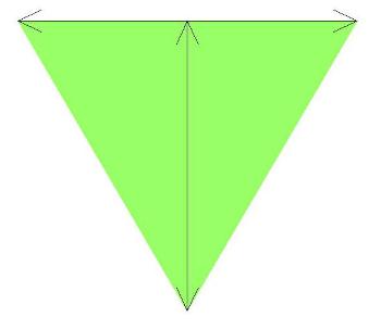
As you can see, the green shaded area is the
ghost’s room to fly around in.
I tried to figure out a method to make a square
flying area, but decided to use the Keep It
Simple Stupid technique.
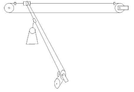
My preliminary sketch of the pulley system for the
controlled ghost flying. The left/right line has limit stops for
end of movement. The in/out line connected to the
left/right line has a slip mechanism for the ghost when it
gets to the end of its movement.
As you can see, it does use some aspects of the Axworthy
flying ghost system, but provides more than just a single
path to follow.
The tensioner shown here is just something to put on
paper, so this could change when I get around to building
this.
Some preliminary specs:
Pulleys
- 12″ – 16″ in diameter for the drives
Motor
- Decent flying speed, so would like 200 rpms or better. Ideally, I would like to hit 15 feet per second at full speed which would be zooming along pretty good. Well, that was a good idea I thought, but ended up slowing it down more to make it more controllable.
I decided on this motor from Surplus Center. Will report on whether it was a good choice
or not.
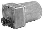
Motor specs:
- 185 RPM Reversible
- 115 VAC Shaft 1/2″ diam. x 1-1/8″ w/flat
- 0.85 amps 4 hole face mount
- Intermittent duty 6″ x 3-1/2″ x 3-1/2″
- Shpg. 10 lbs.
Got the motor in 12-10-04. The torque with a 12″ pulley seems fine by applying ‘palm
pressure’ to it. The motor noise is acceptable to me as it doesn’t get the ‘geary’ sound. It
just sounds more like a louder Dayton motor.
It changes direction directions nicely and with good torque during that too.
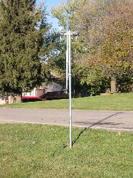
So far (Dec 29th, 2004) I have the main left/right line up in the shop. The pulleys are only 18′ apart, giving a run path around 16′ or so.

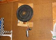
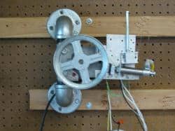
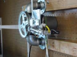
Here is the drive wheel set-up on the west side of the shop. At this time I was using a toggle switch to run it. I haven’t decided on end of run stopping yet for this part as the ghost can get wrapped up
around the pulley at times. I am using 50lb fishing line at this time.

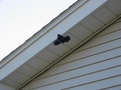
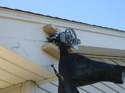
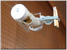
The free wheel on the east side of the shop was made so it could take out any excess
slack on the line. The pulley can be tightened manually with up to 6″ of movement.

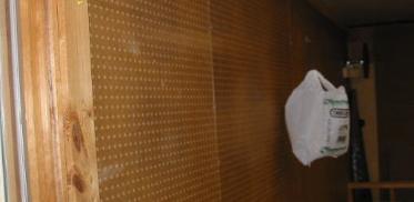
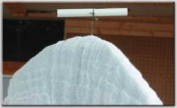
Here is the ghost, a hardware store plastic bag.
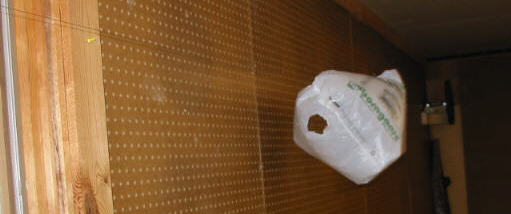
Flying towards you.
And away from you upon mouse over It travels around 10 ft/sec.
A brake mechanism was added to the drive pulley so when the “end-of-run” switch is tripped it would kill the motor and stop the pulley.

I didn’t have any solenoid actuators laying around, so I built up an elaborate pneumatic stopper with some spare parts I had laying around to see how effective this would be.
The drive pulley stops on a dime when the end of run switch is activated, but the inertia of the free pulley kept the line and ghost traveling around a good foot or so.
When the electric pull solenoids come in, they will replace the above set-up on the drive pulley and will add one to the free wheeling pulley to stop the ghost line.
Its specs should provide the force needed to act as a pulley brake and will make the set-up much easier than the above pneumatic one.
Nope, didn’t work as well as I thought, so the air cylinder stayed.
I want the across line perfected first before adding the in/out line. A possible mistake, but I do/did have 301 days till Halloween at this report entry.
Here are the pics of the final testing set-up.
Shown here is the left/right line set-up. I ended up changing to a 6″ pulley to slow down the ghost to make it easier to control.


If the line pulley travels too far either left or right, the ‘end of run’ limit switch will stop the motor in that direction and activate the air cylinder to stop the line more quickly. The bolts act as a line guide for the 50 lb fishing line, otherwise the fishing line would be pulled over too much and jump off the pulleys.
Maybe by adding some end cushions for the line tightener/pulley mechanism, the pulley brake may not be needed.
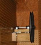
The line tightener/pulley is shown here which is part of the left/right line. A little crude, but it gets the job done.
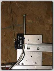
A couple back shot photos showing the limit switches for the end of run stopping.

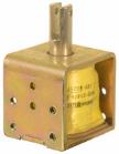
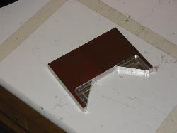
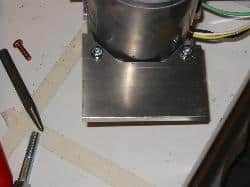
Here is one of the motor mount brackets I milled up for future mounting onto whatever I pleased.


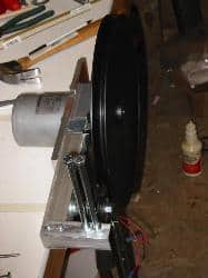
Here is the motor/pulley set-up for the second line that moves the ghost in and out. Here too, I went to a smaller pulley for less speed.
The small middle pulley was needed to wrap the line around the bigger pulley for better traction. Not shown, I did glue in a leather cord inside the larger pulley otherwise the line would still slip due this line does not have that much tension on it.

Due to the geometry of this set-up. The in/out line is shorter at the middle of the left/right line and needs to lengthen out when it gets to either the far left or right side.
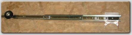
The slack adjuster is made from 2 drawer slides. The photo above is a single slide and I ended up adding a second slide onto for more travel when/if needed later on. An earlier pic with the larger pulley on then, but it does show the 2 bolts mounted up front to act as a line guide for the in/out line.
The in/out line doesn’t have any limit stops like the left/right line due to the length changing and was just more complicated to add.
The line travels through a plastic tube instead which allows the ghost to stop at each end but the line still travels on. I did add a piece of leather inside the tube for a little grippage.

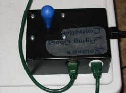
Currently, the ghost is controlled manually by this home-made controller. The joystick is from Happ
Controls and the enclosure box was from RadioShack. Inside, there is a 110 to 12vdc adaptor to provide the joystick with low voltage for it and then the relays switch the neutral portion of the motors for the correct direction running.
I used 3 prong cords for making it easy to move and plug-in. As below in the wiring diagram, I did use the green wire as a neutral and used plastic nuts and bolts when I mounted the 3 prong outlets instead of metal ones.

The schematic shown here has the joystick to the relays
and out to the left/right line motor and limit switches
wiring diagram.
It doesn’t show the in/out motor control, but all that
required was another set of 12 volt relays and cord to
control that motor minus the limit switches and solenoid
connections. If you can figure out this drawing, the
in/out wiring should be easy.
NOTE: I did use 3 prong cords for making simple plug
connections and the green wire is NOT an earth ground
any longer, I used it for the second neutral needed for
the reversible motor.
Final Design