
Another mechanical creation of mine, you’ll get a kick out of these. Designed to be used at any angle or position and remarkably compact, these legs are a great way to add an animated touch, and possibly some humor.

Materials & Tools
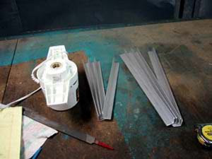
Required Materials
- ~10 ft angle aluminum
- ~7 ft x 1 in. flat aluminum
- Box of 1/4 in bolts, and nuts
- (12) 3/8 in nuts
- 4 eye bolts
- Ice Cream Motor
- Aluminum tube (steel tube if you can weld) that fits snugly into the motor
- (2-4) small pulleys
- Long 1/4 in bolt, assorted washers, two nuts and a large washer
- 10 ft 3/4 in PVC
- 1 ft 3/8 in ready-rod (threaded rod)
- 2 straight connectors, 2 45° connectors
- HUGE pair of cheap pants (men’s 48)
- (2) 5 in springs – contracting
- Very stiff wire
- 4 ft nylon rope
- Creature feet
Tools
- Drill
- Lighter
- Hacksaw
- Wrenches
- Welder (optional)
Step 1:
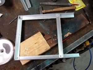
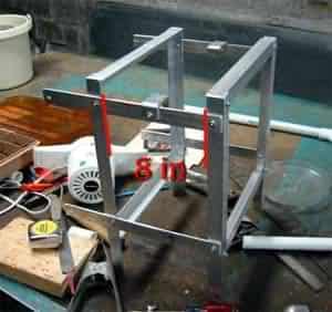
Construction of the frame is pretty straightforward and the pictures will do a good job of explaining it. The sides of the frame consist of two different lengths of angle aluminum. The horizontals are 12 in long and the verticals are approx. 16 in. Two sides are built and later connected by 4x 12 in lengths of the flat aluminum.
Step 2:
NOTE: 3/4 in was the size of tube that would fit snugly into my motor. Some motors come in different sizes, make sure to get your tube to fit this size and substitute your size in every place I mention 3/4 in.
This summer I had the ability to utilize my grandfathers workshop. So for my crank I took a 3/4 in steel tube and cut it, bent it, and welded it. Chances are many of you won’t have these same tools so instead you could take a 1 ft piece of aluminum tubing, measure 6 in from one end, draw a mark, measure 3/4 in, draw another mark, and finally measure another 1 in and draw a last mark. Cut your tube off at this final mark.

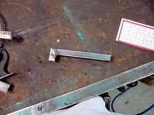
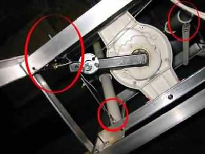
In the picture to the right you can see the layout of the washers, bolt and nuts. The only difference is that the large washer only requires two holes on opposite ends and they should be larger in diameter than shown. When this step is complete using a typical crank washer stack you will have a motor with a functional 6 in crank.
Step 3:
Here is where you assemble the sides of the frame, cut your flat stock into 4 pieces 1 ft long. Drill holes and pieces as shown in picture below…
I left extra space out of the one side so I could decide on how deep the props needed to be, then you need to construct our mounts for the legs.
¨
The picture above shows a side view of what we want to mount our legs to. Unfortunately I forgot to take a photo from above, but the photo from the front will suffice. First, drive a 3/8 in hole through the center of each of the straight PVC connectors. Then run the rod through a hole drilled in the middle of the bar, as pictured in the left, run a couple bolts on, then a pvc connector, another couple bolts, another couple bolts, the connector, another couple bolts and through the other side. Adjust the bolts to hold the connectors where you want them (2 in from each side) and tighten the bolts against each other. Make sure to leave enough slack so that the connector can spin freely.


Step 4:
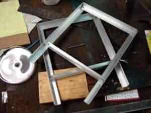
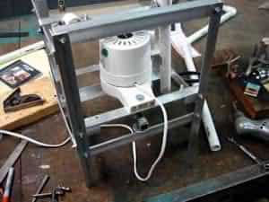
First of all, before you mount the motor you need to assemble the crank. Insert the crank into the motor and wedge some tin scraps in along the side so that the crank doesn’t fall out. This can be done by cutting a scrap 1 in by 3/4 in (or your size) and tap it into a slot with a screwdriver and a hammer. This isn’t guaranteed to keep your crank in 100% of the time, but I don’t think that any epoxies I know of would work. After that is wedged in cut a couple more pieces of your angle aluminum to 11 1/2 in so that you can create a mount for our motor. Then cut out the sides like in the picture below, without the slots the crank may bind up if the motor happens to rock too much, just a precaution.
First mount the bars across the frame so that the crank will clear the bottom part of the frame with at least a half inch of clearance. Bolt them to the frame, set your motor on top and make sure that the crank has a clear path to travel. Go fetch your tape measure and get the motor as close to centered in all directions possible, drill holes through the plastic and the frame and mount it with some long screws. Get a hacksaw and cut off the ‘wings’ of the motor and WHEW! you are done with the hard part.

Step 5:
Be A Friend…Donate some Legs…
A quick and simple part, constructing legs from PVC, here is the sizes you need: (2) 8 in (or 6, forgot to measure) , (2) 1 ft , (2) 1 1/2 ft. The 8 (6?) in pieces go out of the bottom of the connector, drill a small hole through the bottoms of each, you will be connecting wire there later. The 1 1/2 ft pieces go out of the top connector, followed by the 45° connectors and followed by the 1 ft pieces. The 1 ft pieces should also have small holes drilled through their bottoms to attach the feet and pants later
Step 6:
Pull the legs out of the connectors to make the next part easier to do. Drill two holes out of the back of the frame (whichever side is your back) in line with the center of your leg connectors. Then run a bolt through each and screw a nut on loosely. Then run your springs from the 8 or 6 in piece of PVC up to these bolts, this will give the legs their ability oscillate and move with the rotation of the crank later. Now on the back side of the front you need to mount your pulleys. You can do this by drilling a hole on the front-bottom part of the frame, and the front of the bar that the motor is mounted to. Run eye bolts through them and attach your pulleys to them with wire.
TIP: Melt the ends of the nylon rope with a lighter to create a secure bondrun cable
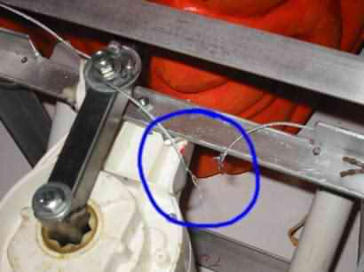
Here you can sorta see how I mounted my pulley, the wire shown here is actually aluminum cable, but I would recommend using a thin nylon rope, reasons for this will be discussed later. Also shown is how the springs are attached and how the cables are looped through the PVC and soldered/melted together. As you can see the crank has four holes, the reason behind this is that by running the cable through one hole and out the other keeps the BINDERS from getting tangled up on the crank. The cable runs from the crank to the bottom pulley, then up through one directly above it, and over to the end of the PVC pipe. As you can see in the picture the crank is as at it’s closest reach to the pulley, run the rope here and tape it to the PVC, then turn the crank 180° to its maximum reach and see where the PVC has swung over to. Adjust the rope until you have the to-and-fro reach balanced and melt the nylon ends together, continue with the other side. Adjust anything that may become a problem and test it!
Here’s a video of mine in testing…
Step 7:
Do These Make My Butt Look Big?
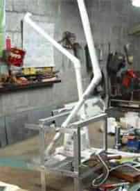
Now comes the finishing touches. Run the pants over the frame and adjust the belt (a belt is needed, or just use rope) run it a bit to make sure that the crank isn’t going to hang up on it. Good, now take a pair of scissors and cut slit through the hem on each pant leg and run the stiff wire through it. This will allow the pant legs to stay open and gives us a way to attach them to the PVC. Remember way back when you drilled holes through the ends of the PVC legs? Now what you do is measure the diameter of the pant legs, add a half inch, and cut a stiff piece of wire and straighten it out. Run this wire through the holes and pull the pant legs over it to keep the legs open and seemingly suspended in thin air. Now I would recommend running the prop for a little bit to make sure it doesn’t get tangled up on anything. Now here’s a picture of my legs with the pants attached…

Step 8:
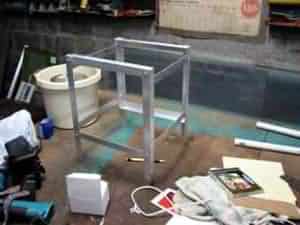
Now attach your creature feet by running the straight piece of metal wire at the ends of the legs through the ankle area, mount it up so it won’t disassembledtip over and give it a stress test for 4 – 6 hours keeping an eye on it to see if any problems arise and give it a complete inspection to see sign of wear and tear. The really great thing about this project is how little space it actually takes up…I knocked my head for a couple days figuring out the best way to design the prop to meet this goal. To store it remove the pants and pull the legs out. If the legs are stuck a great tool for wrenching around PVC is a mouse pad, trust me, the ones with rubbery bottoms work quite well. Unbolt the two bars that attach the motor to the frame and put the nuts and bolts in a plastic baggies. Loosen the 8 bolts that attach the front and back of the frame together and collapse the frame, keeping the motor sandwiched between. Stick the plastic baggie in a pants pocket, flank the motor with the legs, and wrap the pants around the frame and secure with wire, here is a picture of how small the prop can be collapsed down to.
Video of Completed Prop

And you are DONE!!!
But there are always things that go wrong and designs that need to be changed to here are some things you should keep in mind and various problems that I had…
The original idea I had for the leg was to be sticking out of the ground, as though somebody had been planted in upside down, but the additional weight of the feet and the slope of our yard proved to be too much a match for the springs I was using.
When trying to plant the frame into the ground it tweaks out of shape easily, diminishing the range of motion for the legs, this can be solved by attaching a flat aluminum piece from the rear-top corner to the front-bottom corner, and the opposite direction on the other side.
To solve the above problems we ran the legs out of a tree in our front yard and it worked well for a couple hours, then one leg stopped kicking, followed by the other an hour later. At the time I was confused as to why one stopped instead of both, it was mind-boggling. Upon inspection I found that the aluminum cables I had been using actually shredded! I was not expecting this since there was no sign of damage earlier. For this reason I am promoting the use of nylon rope, I have yet to test it extensively, but I believe that it will work just fine.