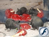
Rat Feast was a subtle but effective addition to our 2005 Dungeon scene. Sitting off in a corner, four rats are calmly chewing on a half eaten human leg. The glowing eyes and the subtle up and down movement of the rats was very effective and garnered a lot of positive comments and a few shrieks. Rat Feast was fairly simple to construct, took two evenings to complete (about 4 hours) and performed 100% reliably.
Materials Used
- 24V DC Gearhead Motor
- Vinyl Squeaking Rats
- LEDs
- Resistors
- Plastic Gears
- Picture Wire
- Coat Hanger Wire
- Eye Bolts
- Crimp Ring Terminals
- Washers
- Nuts/Bolts
- Great Stuff Foam
- Chcken bones
- Plywood
- Broken/hollow mannequin leg
- Leg from old pair of jeans
- Red & Grey Paint
- Hookup Wire
- Glue
- Tools Used
- Drill
- Jig Saw
- Screw Drivers
- Pliers
- Wire Cutters
- Wire Crimper
- Soldering Iron
- Paint Brushes
Assembly
The pictures pretty much tell the story of this prop. A small motor turns a crank (or two in this case), wires are connected to the crank using ring terminals and then routed through eye hooks to each rat. The rats have their tails screwed down to the base board. Because of the design of the rats, this lifts their front feet off the board about half an inch. When the motor rotates, the flexible vinyl rats get pulled down as if they are taking a bite out of the flesh and as the motor comes back around they return to their original position. The following is not a step by step instruction guide, so be sure to read through it all before beginning.
I started with a piece of 16″x15″x3/4″ plywood for a base which I painted grey. Of course the dimensions and color can be changed to suit the layout and needs. 3/4″ thick plywood was used simply because it was available.
All haunts need rats and since I tend to give a number of these away each year as souvenirs I needed a source for cheap, decent looking rats. I found this at Oriental Trading. 6” vinyl squeaking rats with a 12” tail.
The motor was salvaged from a junked laser printer but I’m sure that any DC gearhead motor of the appropriate RPM and torque will do. This is a 24V motor but I found that at 12 volts it rotated at 50 RPM and had plenty of torque to do the job. This seems to be the near perfect speed. Much faster and the rats look like they’re on Meth, much slower, Valium. Since 12 volts is the standard low voltage of our haunt this worked out quite well. A possible alternative motor might be this one from Electronic Surplus Inc.
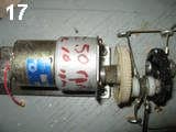
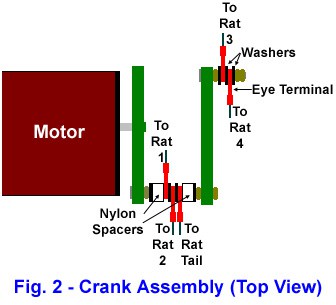
The crank was made using a plastic gear and a bolt. Since I didn’t want all four rats to be eating in unison I added a second plastic gear and bolt assembly to the end of the first to crank.
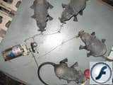
The diagram (Fig. 1) and pictures 8, 16, 17 & 18 should give a clearer idea of what was done.
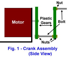

Since the shaft of the motor I used was tapped, the crank assembly was simply screwed onto the shaft. This of course will need to be varied depending on the shaft of the motor used.
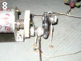
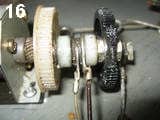
The wire used to connect the rats to the crank was 20 lb. braided picture wire. A fairly large ring terminal (such as Radio Shack part #64-3040 for example) was crimped to the end of the wire and slipped over the bolt of the crank. Remove the insulating plastic from the terminal. The eye terminal needs to be large enough so that the crimp end does not interfere with the crank assembly. The terminals are separated from each other on the crank using nylon spacers and/or washers as needed. Have a look at pictures 16 and 18.
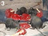
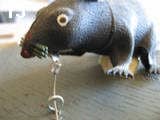
Routing the wires to the rats is going to be dependent upon the layout of your rats and the object they are eating. We were fortunate in having been given a number of surplus mannequins from a department store and a quantity of broken mannequin parts. One of these parts was a hollow leg. This allowed me to route most of the wires through eye bolts on top of the board to the rats and the wires and eye bolts would be hidden under the hollow leg. This wasn’t possible with the rat (Rat 4) enjoying his morsel off on his own (see pictures 3 & 7).

In this case the wire was routed from the crank through a hole drilled in the base and up through another hole to the rat. Small feet were added to the bottom of the base to give clearance for this wire (pictures 8 & 19).
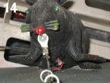
Once the wire has been routed to the rat it was then cut to size and another, smaller ring terminal was crimped to the end. This ring terminal was attached to the underside of the head of the rat with a self-tapping wood screw (pictures 13 &14).
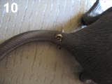
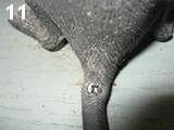
This arrangement held very well. The crank was then moved to its furthest position for the rat being worked on and the final positioning of the rat was done to make the wire reasonably but not overly taut. A self tapping wood screw was then driven through the base of the rat’s tail into the wood base (see pictures 10 & 11).
As mentioned earlier, to make the rats not look like they are eating in unison, two cranks were used. Two rats were connected to each crank so that two rats are down getting their next bite while two are up chewing what they have. To further the effect, the rats connected to each crank are on opposite sides from each other (see the video to get a clearer idea). If the crank assembly can be made strong enough and the motor has enough torque there is no reason why additional cranks could not be added to the assembly. Once all the wires have been added, an acorn nut, or lock nut or (as used here) two small nuts tightened against each other is used to prevent the wires from coming off the end of the crank but still allowing them to turn freely.
Generously lube the wires, eye bolts and crank with WD40 or similar, power the motor and make any final adjustments that may be needed. Watch a Flash movie of the mechanism in action.
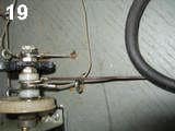
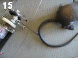
Our version of rat feast has one of the rat’s tails moving as well as the heads. This was accomplished by using a piece of stiff coat hanger wire from the crank (again using an eye terminal) to the tail. The connecting end of the wire was given a short bend, forced into the vinyl tail and glued in place. The tail tip was also glued to the base. See pictures 15, 19 and 20 to get a clearer understanding of this simple but effective addition.
Another optional extra in our version of Rat Feast is the glowing LED eyes in three out of the four rats. Hookup wire was soldered to the LED terminals. A hole the size of the LEDs was drilled through the rat’s eyes and another hole was drilled through the rats belly. The wire was run through the eyes and then down through the hole in the belly and then through another hole drilled under the rat in the base. A length of coat hanger wire and some tape makes this job easer. The resistors for the LEDs were added under the base and the LEDS were wired into the power system.
The gore the rat’s are feasting upon has unlimited possibilities to let your imagination run wild. About the only things to keep in mind is that you want the gore to hide the mechanism and wires as much as possible but at the same time it can’t interfere with the movement.
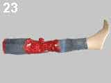
Our version uses a hollow mannequin leg cut down so it sits flat on the base. About a third of the leg was cut away and replaced with gore. The leg from an old pair of jeans was added for effect.
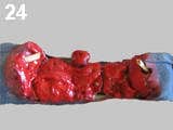
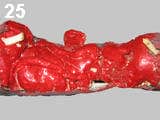
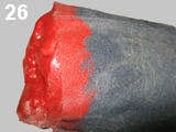
The gore was created using Great Stuff expanding foam. It was simply sprayed from the can onto an old piece of wood. A number of separate piles were sprayed out to give us a choice for the final gore. A few of these piles had chicken bones added to further the effect. Once the foam had set, the pieces were selected and trimmed as need.The gore was painted using gloss red enamel paint with a couple drops of blue added to darken it up a bit. Once the paint had dried the gore was fitted into place and coated with two coats of clear gloss polyurathane to preserve the shinny fresh gore appearance (see pictures 23, 24, 25 and 26).
That’s it. It took much longer to create this explanation than it did to create the prop itself.