
As the trick-o-treaters walk up the path to the house, a headless dummy lying in the yard flails its arm at them. Its hand hits the ground as close as a foot from their feet. A moment later the arm raises back up again. This has made adults leap into the air, and kids fall down!
We made the left foot stick up by simply pounding a small stake into the ground and slipping the shoe over it. For something so simple, it makes the dummy seem far more real.

After someone stepped on it causing it to jam, Tony built a wooden box around it strong enough to stand on. It raises like a car hood.
The Flailer is triggered by a light beam sensor and uses a single geared 12v DC motor to cock and release the arm which is flailed out by a pair of spring-loaded door hinges which form the elbow. It’s computer controlled, but it didn’t have to be. We did it this way because it allows the timing to be adjusted easily, allows us to count the number of times the beam is broken, and we just wanted to because it’s really cool!
After the Flailer is triggered, the computer waits about 45 seconds before letting it go again. If it went off every time someone walked past it, it wouldn’t scare anyone because they’d all see it get the people ahead of them. It’s also a lot of fun to frustrate people’s attempts to figure out what triggers it! In 1997, a father tried to show his kids how it worked. He walked up and down in front of it for the full 45 seconds and nothing happened. Just as the kids lost interest and turned away, it went off!
The metal lever rotates freely on the wooden base which is attached to the motor. As the base rotates, a screw sticking up from the base catches the lever and pulls it around raising the Flailer’s arm. The motor is stopped just short of pushing the lever all the way around. To release the arm, the motor simply starts running again and pushes the lever past the critical point. Then the lever is pulled around, away from the screw, by the arm’s elbow springs.
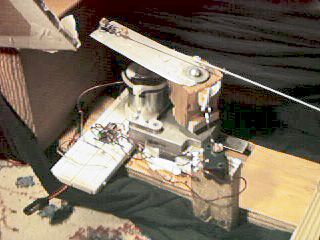

A pair of long springs in the bicep part of the arm pull the cord into the bicep in both directions to keep both ends taught at all times. This prevents the cord from getting tangled up with the lever or coming off the block of wood near the elbow which gives more leverage to raise the arm when it’s extended.
When power is supplied to the flailer, it flails its arm and then raises it to the cocked position and stops by itself even though the power is still on. This is accomplished by a subtle control circuit designed by Tony. In the cocked position, a limit switch is pressed by a boom sticking out of the wood base which is attached to the motor. When the power comes on, the motor turns the base releasing the arm and the limit switch. The switch then turns on a relay which latches itself on until the power is cut. With the relay on, the limit switch will now cut the power to the motor when it rotates back around to the cocked position. The computer only needs to supply power long enough for the cycle to be completed. This way we save an input line on the computer and only two wires need to be run to the flailer.
The beam emitter is a red “super bright” LED on the end of a cylinder which slides inside a tube. The tube has a 1″ plastic lens mounted in one end. The cylinder slides in and out to focus the beam. The end of the tube is cut at an angle to form a hood which hides the glare of the light from eye level. At 25 feet, the beam spreads out to about a meter in diameter, but it’s still bright enough to be detected. Since the beam is diffuse, it can’t be seen hitting people’s legs the way a laser would. We’ve used this for three years now and nobody has seen the beam.

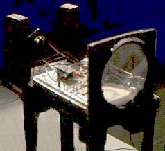
The receiver uses a 3″ plastic lens to concentrate the diffuse light beam onto a CdS cell which is mounted on a bendable wire for focusing and aiming. The voltage passed by the CdS cell when the beam is unbroken keeps a transistor off. When the beam is broken, the transistor comes on and activates a relay which latches itself on until reset by the computer. A cover (not in the picture) has a red filter, and a tube on the front to restrict the sensor’s field of view.
The sensitivity has to be adjusted to match the ambient light level. We adjust it for night, so it doesn’t work until it gets dark out. This could be solved by using a light beam with oscillating intensity and detecting the frequency rather than just the light level, but I haven’t taken the time to learn how to do this yet.